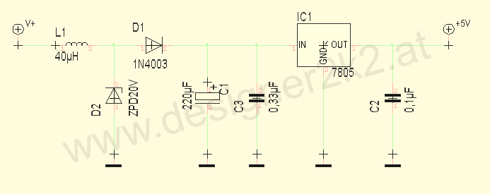
I am trying to build an arduino for my car to monitor some temp gauges, I need to get a clean voltage to the arduino and I have read a ton of different opinions. I was looking for some suggestions to get a clean 5V to the unit, this is a schematic that I found, are all of these components necessary? what is the purpose of the inductor and where are there 2 caps before the input of IC1?
Announcement
Collapse
No announcement yet.
electronics gurus
Collapse
X
-
electronics gurus
Interested in being a VIP member and donating to the site? Click here http://dfwmustangs.net/forums/payments.phpTags: None
-
0.33uF cap, C3 and 0.1uF cap, C2 are recommended values on the LM7805 data sheet, so they would be pretty standard thing to add. This is to smooth any input and output ripples on the voltage.
D2 is a zener diode that protects the rest of the circuit from over voltage - limiting it to 20V.
The inductor and 200uF capacitor, C1, work as temporary energy storage devices that smooth fluctuations in both input voltage and current. More specifically, they protect the voltage regulator from inrush current and overvoltage when a load is placed on the output terminals of regulator.
The diode, D1 protects the voltage regulator from a reverse current that the LC filter might create.Men have become the tools of their tools.
-Henry David Thoreau
-
Originally posted by BERNIE MOSFET View Post0.33uF cap, C3 and 0.1uF cap, C2 are recommended values on the LM7805 data sheet, so they would be pretty standard thing to add. This is to smooth any input and output ripples on the voltage.
D2 is a zener diode that protects the rest of the circuit from over voltage - limiting it to 20V.
The inductor and 200uF capacitor, C1, work as temporary energy storage devices that smooth fluctuations in both input voltage and current. More specifically, they protect the voltage regulator from inrush current and overvoltage when a load is placed on the output terminals of regulator.
The diode, D1 protects the voltage regulator from a reverse current that the LC filter might create."If I asked people what they wanted, they would have said faster horses." - Henry Ford
Comment
-
Originally posted by BERNIE MOSFET View Post0.33uF cap, C3 and 0.1uF cap, C2 are recommended values on the LM7805 data sheet, so they would be pretty standard thing to add. This is to smooth any input and output ripples on the voltage.
D2 is a zener diode that protects the rest of the circuit from over voltage - limiting it to 20V.
The inductor and 200uF capacitor, C1, work as temporary energy storage devices that smooth fluctuations in both input voltage and current. More specifically, they protect the voltage regulator from inrush current and overvoltage when a load is placed on the output terminals of regulator.
The diode, D1 protects the voltage regulator from a reverse current that the LC filter might create.
Interested in being a VIP member and donating to the site? Click here http://dfwmustangs.net/forums/payments.php
Comment
-
Originally posted by Mach1 View PostThanks for the explanation, it is calling for an ultra low esr cap for C1, any reason why, also I am looking at replacing IC1 with a R-78xx DC to DC converter, would it just be a drop in or should I modify the circuit for the converter?
http://www.recom-international.de/pd...R-78xx-0.5.pdf
Resistance translates into power dissipation - heat - and too much can alter the capacitor's behavior or lead to failure. You can have a capacitor still appear to be functioning with correct capacitance, yet still be the faulty element of a circuit because the failure mode is an ever increasing ESR.
To answer your question more directly, I'd guess that the ultra low ESR is important because of the ripple from the alternator. I don't think there is anything else to smooth the dc voltage than the rectified 3-phase output. As-is, I think this puts about a 0.8V ripple out across the 12-14 Vdc line. This heats the capacitor up and, given that its purpose is to help protect the rest of the circuit, it helps to have a low ESR to keep the power dissipation low.
The R-785.0-0.5 would be a good alternative, but you'd want to change C3 in the circuit above to a 4.7uF~10uF electrolytic capacitor.
The data sheet calls for a 1-Ohm resistor to be placed in series with C3. You want C3 to be very close to the input terminal of the R-785, so this series resistor should connect from the cathode of the capacitor to ground. I'm guessing this is to increase the apparent ESR that the R-785 would see on the input, but I'm not entirely certain this is the case.
C2 would not be required. The Arduino will likely have its own voltage regulation to handle noise on the power input. The data sheet says the typical output ripple is 20mVp-p without a capacitor, which is about 1% deviation from 5Vdc. That's not bad at all.
You might also add a schottky diode in series with the output like shown in option 2 on page 1-5 of the datasheet. I'd go with something like a SB560 http://www.vishay.com/docs/88721/88721.pdf.Men have become the tools of their tools.
-Henry David Thoreau
Comment
-
Reminds me of my old electronics instructors response to any question we had in class... Its FM.
Fuckin Magic../ ____ _ _\.
(]]]_ o _[[[)
\o_FORD_o/
|__|.....|__|
God closes doors no man can open, God opens doors no man can close. Revelations 3:7-8
Comment
Comment