Very nice!
Announcement
Collapse
No announcement yet.
1990 Coupe - 'budget' turbo kit
Collapse
X
-
Looks great as always Brooks. Don't you hate things like that brake rod? Trying to explain to someone that you spent however long to make something "right"?sigpic18 F150 Supercrew - daily
17 F150 Supercrew - totaled Dec 12, 2018
13 DIB Premium GT, M6, Track Pack, Glass Roof, Nav, Recaros - Sold
86 SVO - Sold
'03 F150 Supercrew - Sold
01 TJ - new toy - Sold
65 F100 (460 + C6) - Sold
Comment
-
Man, it didn't take too long really.. .and probably would have worked as is, but made the pedal a bit too low for my taste. Making the rod longer actually keeps the brake rod from coming out, even without the pedal stop. (the brake arm hits the column mount if you pull it back towards the seat, but I put the bolt in there anyways.)Originally posted by Chas_svo View PostLooks great as always Brooks. Don't you hate things like that brake rod? Trying to explain to someone that you spent however long to make something "right"?
The only real difficulty was that the bolt was hard as hell! I had to cut it pretty slow to keep from breaking the cutter.
Comment
-
I was going to ask about that, as I recall machinist bitching about things like that, but I never get to play on a lathe. I have turned a few things with a drill press, poor-boying the hell out of it.sigpic18 F150 Supercrew - daily
17 F150 Supercrew - totaled Dec 12, 2018
13 DIB Premium GT, M6, Track Pack, Glass Roof, Nav, Recaros - Sold
86 SVO - Sold
'03 F150 Supercrew - Sold
01 TJ - new toy - Sold
65 F100 (460 + C6) - Sold
Comment
-
It was one of those things where i "knew there was a better way" to do it. Once I got tired of taking an hour or more per fit-up, and used what was shown above, it went back to about 15 minutes.Originally posted by Snatch Napkin View PostSweet fab tip on that nut! I've been doing that the hard way for far too long!
Thanks dawg.Originally posted by jason07 View Postdamn! looks good homie!
Comment
-
There's plenty to talk about this time around. I've been busy with other projects, so it's been tough to get anything accomplished that took any serious thinking. Now, I've had some time.
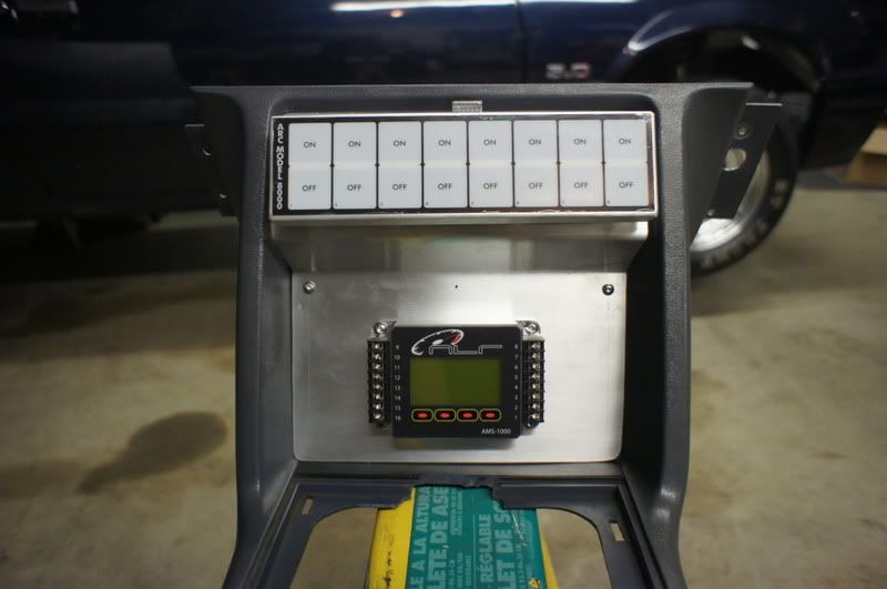
First, the boost controller and ARC switch panel that mounts up in the old HVAC/Radio mounting locations. It's hand formed on a metal bench, as I dont have a brake. It still turned out pretty good. I may get it coated before final install. Not sure yet.
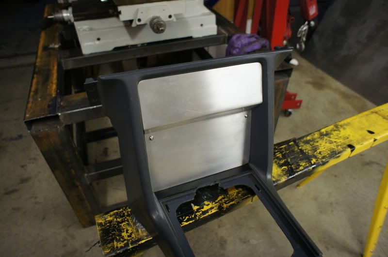
Panel with switch panel and boost controller mounted.
This part took some thinking. I needed a way to make the one-size-fits-all trigger wheel that megasquirt sells to PROPERLY fit my balancer. The only way was to bore the center of the wheel, but alas, that was the problem. HOW to bore the wheel. It's much too thin to chuck up on, spin and hope that it doesn't come out like a 800RPM chinese throwing star. This is how I did it.
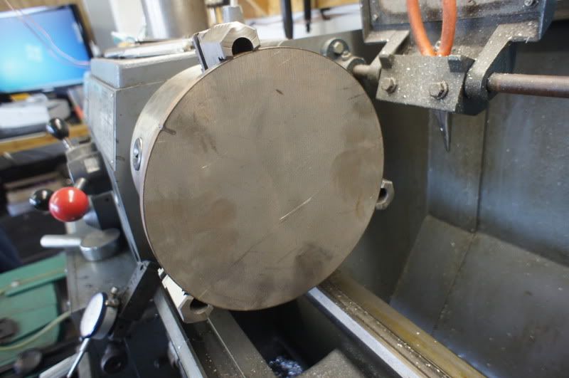
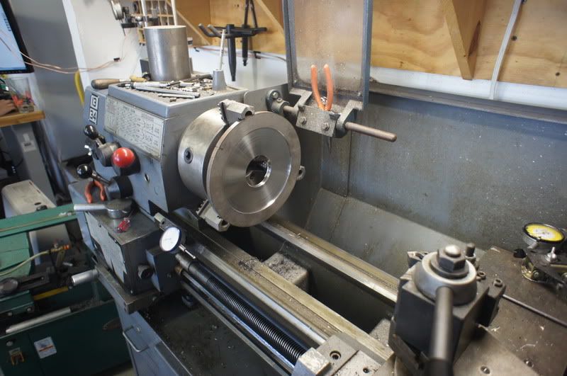
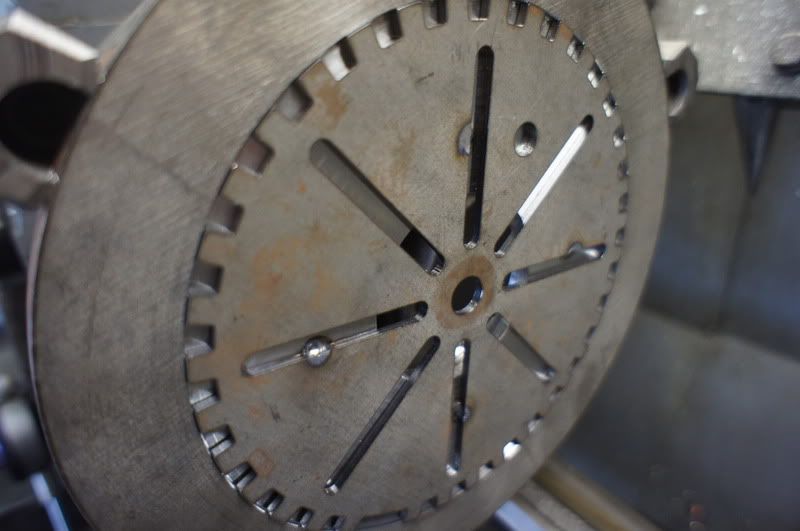
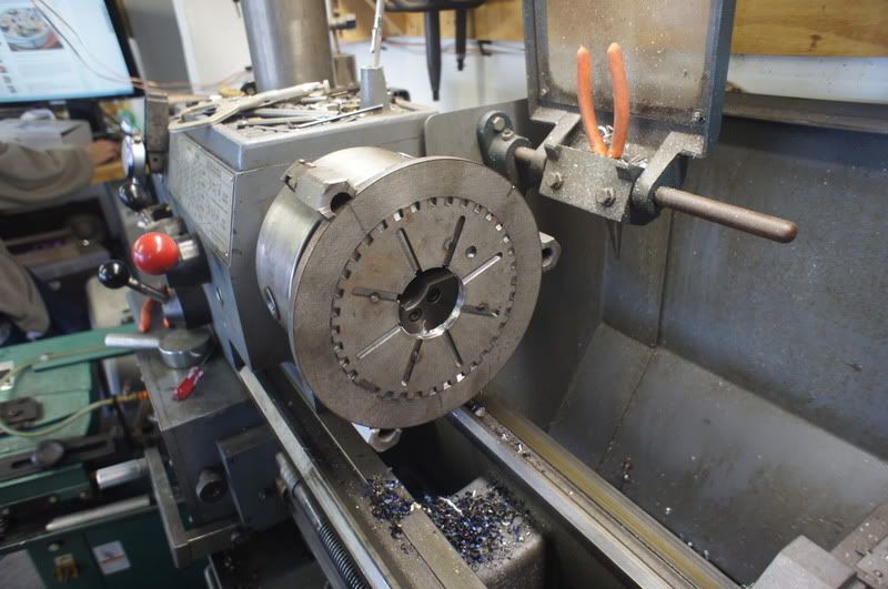
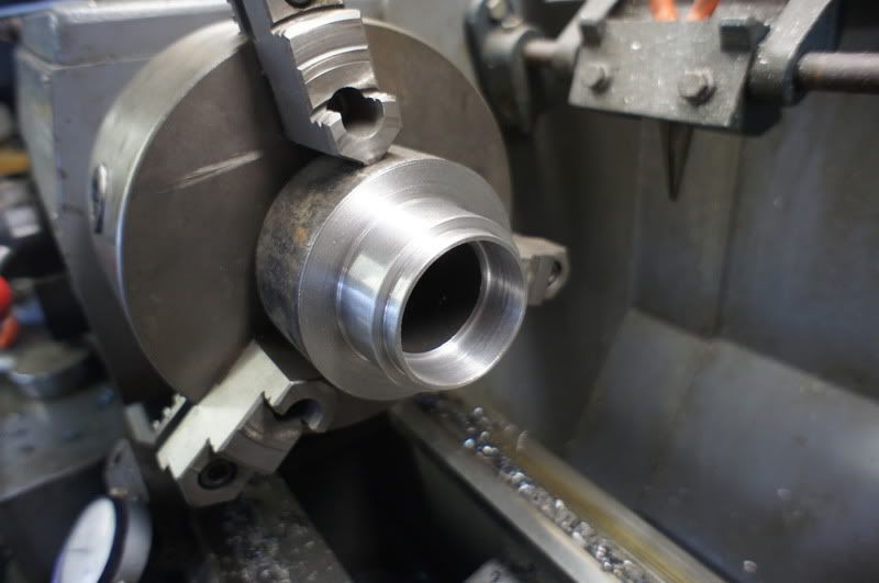
Now that part is all done, I needed a way to center the trigger wheel, the pulley and make it all run very true to the balancer. So, next I machined a sleeve to do just that. Unfortunately, I only got pics of the first lathe operation.
Comment
-
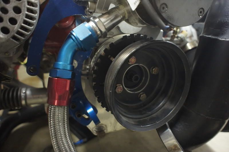
Here's the whole setup mounted. Note the Morose crank trigger bracket... more on that later.
Know what this is?
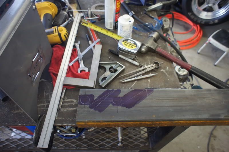
what about now?
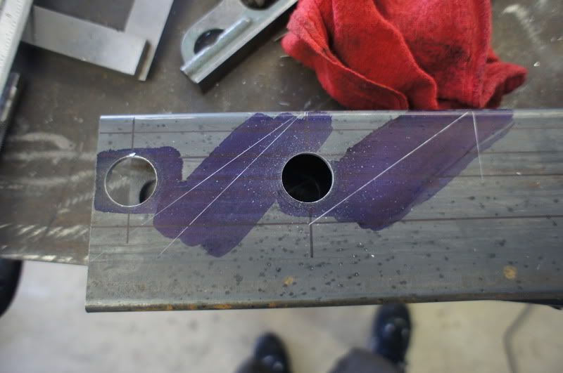
Starting to make sense?
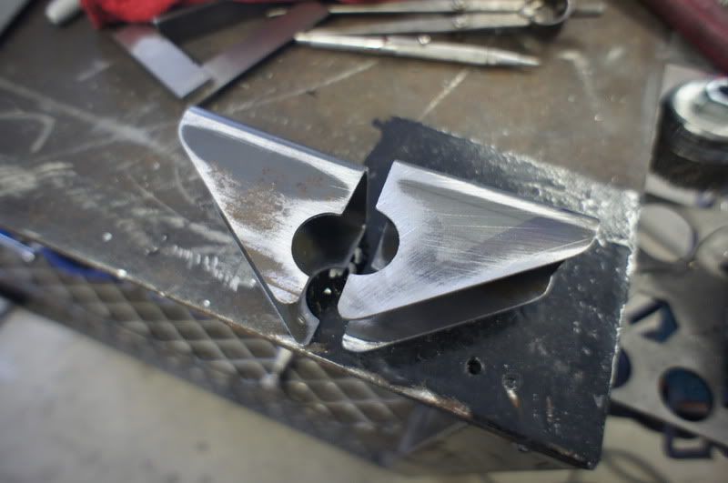
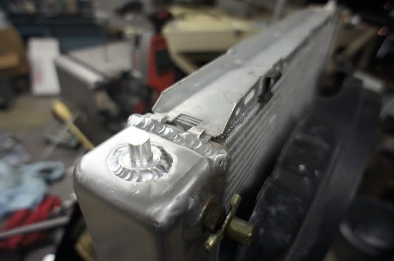
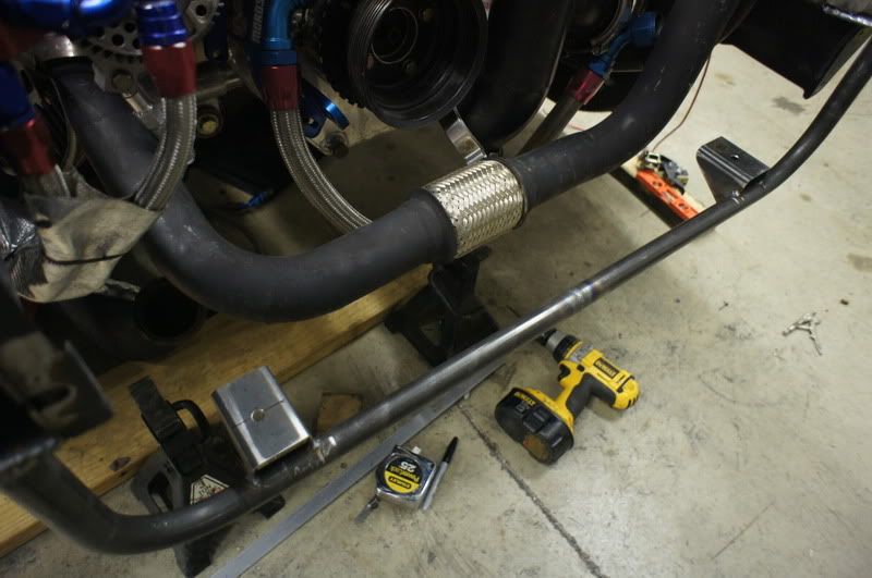
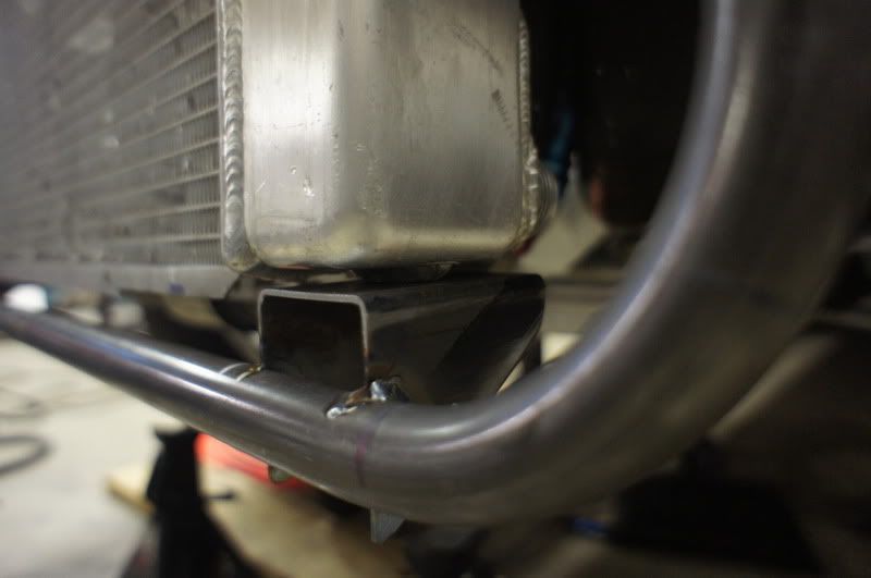
Up close. The top is still secured by the stainless UPR hold down.
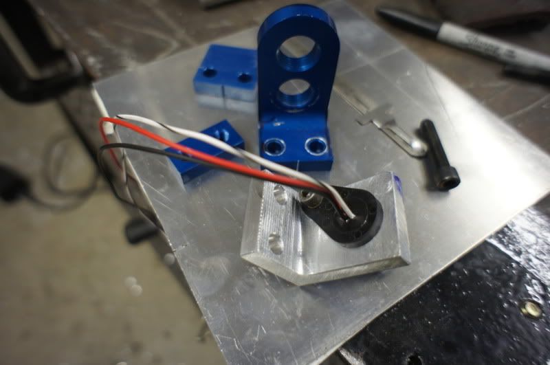
The crank trigger bracket again. I re-did the mounting for a few different reasons. Mainly, I didn't want to alter the crank trigger bracket or sensor, just in case I had to revert to it. It's a different kind of sensor, a hall effect sensor. Now uses a 36-1 wheel instead of the old 4 magnet wheel. Much better.
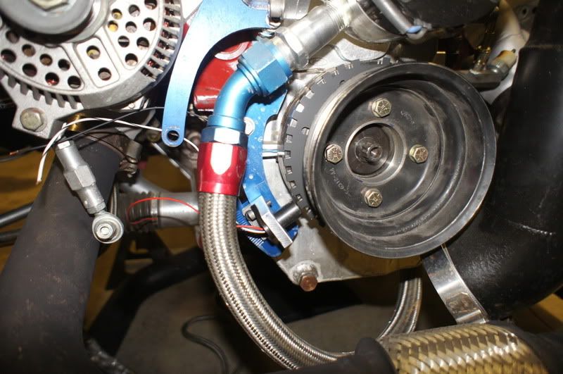
Last but not least, the hall sensor mounted up in it's new home.
Comment

Comment