Announcement

Collapse
No announcement yet.

Hall Effect to VR Speedo sensor

Collapse
X
 
  • Filter
  • Time
  • Show
Clear All
new posts

  • Hall Effect to VR Speedo sensor

    I am yanking out the MT82 in my 2011 and putting a Tr-6060 in it's place, I have a issue with the speed sensor, the MT82 uses a hall effect sensor and the TR-6060 uses a VR Sensor.

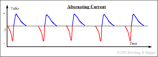
    VR puts out a AC sine wave signal, HE puts out a sqare wave 0-12V DC signal.

    My first thought was using a HEI module, it basically convert a VR signal from a distributor to a sqare wave, anyone have any experience with this?
    Interested in being a VIP member and donating to the site? Click here http://dfwmustangs.net/forums/payments.php

  • #2
    It's funny you should mention this, I went through a similar problem - but with the HEI/VR sensor actually IN the distributor.. only mine was for megasquirt. doh.

    I have a link that may describe the module enough for you to figure out what you need to know..outside of that, I got nothin.


    EFI, Fuel Injection, Auto, automotive, car, TPI, computation, ECU, MegaSquirt, GPIO, MicroSquirt, Sequencer, stim, MegaShift, MShift, DIY, transmission, 4L60E, 4L80E, controller, shifter

    Comment


    • #3
      If all you need to do is convert an AC signal to a square wave, a simple comparator might work. When the AC signal is positive, it'll output 12V, when it is negative, if puts out 0V.

      I don't know enough about the two sensors to say that you won't need any other signal processing. Are the frequencies the same?
      Men have become the tools of their tools.
      -Henry David Thoreau

      Comment


      • #4
        Originally posted by MOSFET View Post
        If all you need to do is convert an AC signal to a square wave, a simple comparator might work. When the AC signal is positive, it'll output 12V, when it is negative, if puts out 0V.

        I don't know enough about the two sensors to say that you won't need any other signal processing. Are the frequencies the same?
        The freq's will prob be diff but I can change that in the computer assuming they are not over or under the computers usable range.
        Interested in being a VIP member and donating to the site? Click here http://dfwmustangs.net/forums/payments.php

        Comment


        • #5
          Ok, if the frequencies get outside the usable range that makes it fun.

          I don't really know what's out there for something like this but if you don't find an off the shelf solution, off the top of my head I think you could do something like a TI LP311 comparator IC (link opens a PDF from TI)

          The basic connections would be:

          1) EMIT OUT to wherever original HE signal Line goes in
          2) IN+ to VR signal line out (limited to 15V peak)
          3) IN- to GND
          4) VCC- to GND (BATTERY -)
          5) No Connection
          6) No Connection
          7) COL OUT to BATTERY +
          8) VCC+ to BATTERY +


          You may want to add some other things to protect the IC a bit more, and give the circuit a better, more robust design. If it's something you want to look at more, and would like my help, let me know.
          Men have become the tools of their tools.
          -Henry David Thoreau

          Comment


          • #6
            Originally posted by MOSFET View Post
            Ok, if the frequencies get outside the usable range that makes it fun.

            I don't really know what's out there for something like this but if you don't find an off the shelf solution, off the top of my head I think you could do something like a TI LP311 comparator IC (link opens a PDF from TI)

            The basic connections would be:

            1) EMIT OUT to wherever original HE signal Line goes in
            2) IN+ to VR signal line out (limited to 15V peak)
            3) IN- to GND
            4) VCC- to GND (BATTERY -)
            5) No Connection
            6) No Connection
            7) COL OUT to BATTERY +
            8) VCC+ to BATTERY +


            You may want to add some other things to protect the IC a bit more, and give the circuit a better, more robust design. If it's something you want to look at more, and would like my help, let me know.
            Great info, thank you! I have heard that at high rpm the VR sensors can output over 50v, I hooked up my MM to the sensor and turned the output shaft with a drill at 450rpm, it was outputting 78hz and 2.0V, It needs to be able to handle the VR signal at 8-9000rpm. What else do you recommend to protect the IC?
            Interested in being a VIP member and donating to the site? Click here http://dfwmustangs.net/forums/payments.php

            Comment


            • #7
              Originally posted by Mach1 View Post
              Great info, thank you! I have heard that at high rpm the VR sensors can output over 50v, I hooked up my MM to the sensor and turned the output shaft with a drill at 450rpm, it was outputting 78hz and 2.0V, It needs to be able to handle the VR signal at 8-9000rpm. What else do you recommend to protect the IC?
              Ooh, does it stay at 78 Hz and the RPM varies the voltage? And does the HE frequency vary as the RPM varies? That makes it a bit harder to do, but it's doable.

              Are you the first person to put a TR6060 in the 2011?

              Other things would be basic voltage regulation in case you get any weird spikes or dropouts in the source.
              Men have become the tools of their tools.
              -Henry David Thoreau

              Comment


              • #8
                Originally posted by MOSFET View Post
                Ooh, does it stay at 78 Hz and the RPM varies the voltage? And does the HE frequency vary as the RPM varies? That makes it a bit harder to do, but it's doable.

                Are you the first person to put a TR6060 in the 2011?

                Other things would be basic voltage regulation in case you get any weird spikes or dropouts in the source.
                "Are you the first person to put a TR6060 in the 2011? "
                As far as I know, yes

                In the VR circuit, its just like an electric motor, you turn it slow it's going to be low hz and voltage, you turn it fast and the hz are high and the voltage is high.
                What matters to the computer is the freq not the voltage, and just the freq in the HE sensor.


                VR


                HE


                This page is a really good read on how the sensors work.
                EFI, Fuel Injection, Auto, automotive, car, TPI, computation, ECU, MegaSquirt, GPIO, MicroSquirt, Sequencer, stim, MegaShift, MShift, DIY, transmission, 4L60E, 4L80E, controller, shifter
                Interested in being a VIP member and donating to the site? Click here http://dfwmustangs.net/forums/payments.php

                Comment


                • #9
                  OK, thanks, that's good information there! I wasn't sure what input format the computer would be looking for. I think the comparator would still work. Since you're concerned about when the signal crosses from positive to negative and not voltage magnitude, you'd want to add something like a 12V zener diode from the VR input to ground which will clip the voltage so you don't exceed the input limits to the comparator.

                  I think the connections I gave work with a leading edge trigger, but that's something that I'd have to spend a little time on to be sure.


                  I don't know how noisy 12V sources are on cars or how tolerant the input terminal would be of overvoltages. I guess they typically can run as high as 14-15 Volts? You could probably put a 15V zener from the Emit terminal to ground to protect the computer input from any spikes or over voltages without interfering with the recharge voltage. I'm kind of just thinking here, not really sure it would do much for you.
                  Men have become the tools of their tools.
                  -Henry David Thoreau

                  Comment

                  Working...
                  X