Announcement

Collapse
No announcement yet.

HID relay harness diagram

Collapse
X
 
  • Filter
  • Time
  • Show
Clear All
new posts

  • HID relay harness diagram

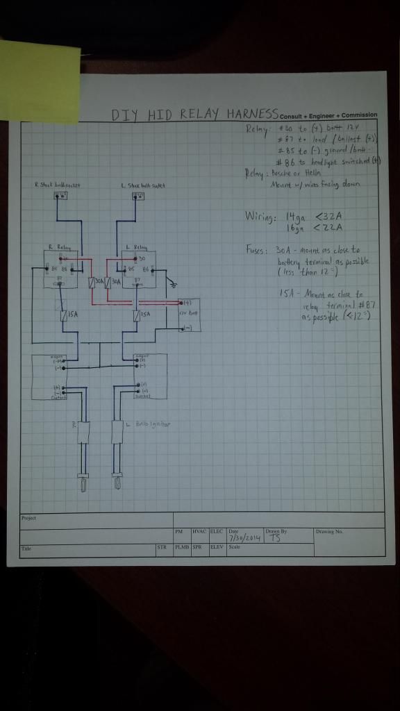
    I ordered a replacement ddm kit after my first kit if 3 years failed. The new kit (same wattage) flickers and I don't want to wait for their dinky harness to ship from China so I'm gonna wire one up this weekend. Im going to use my old kit's connectors to build a true pnp dual relay harness and tidy it all up behind the bumper support. Does this look correct? All input is appreciated!

  • #2
    Any reason for two relays?
    Men have become the tools of their tools.
    -Henry David Thoreau

    Comment


    • #3
      Originally posted by BERNIE MOSFET View Post
      Any reason for two relays?
      When a relay decides to crap out I will still have one headlight. Or should I wire them as 1+1 active redundancy? Or am I overthinking the whole enchilada?

      Comment


      • #4
        I don't think the redundancy is a bad idea. I was just curious about whether that drove the design decision.

        You could make it an active redundancy, but then you need some indicator that the primary failed. That's probably more work than it would ever be worth.
        Men have become the tools of their tools.
        -Henry David Thoreau

        Comment


        • #5
          Originally posted by BERNIE MOSFET View Post
          I don't think the redundancy is a bad idea. I was just curious about whether that drove the design decision.

          You could make it an active redundancy, but then you need some indicator that the primary failed. That's probably more work than it would ever be worth.
          What should I expect to crap out first, the line/load fuses or the cheap autozone relays? I'm trying to prevent having to take it back apart to tinker with it. How would I go about wiring the failure indicator? I like making things complicated.

          Comment


          • #6
            The load will be the same on each side of the relay, if the hid only needs a 15 amp fuse, then a single 15 amp fuse near the battery should be sufficient.

            Comment


            • #7
              Im thinking of wiring the diagnostic led light between the load side and the ground on the relay. So if my ballast fuse fails I will still see the led. If the relay fails my led will be off. Typical for both relays. Why would I not fuse between relay and ballast, David?

              Comment


              • #8
                Relays will fail first.

                If I wanted to make the system more robust,
                I might consider a quality DPDT primary
                relay that, when energized, relays power to
                lights and breaks ground from the
                secondary. If the primary fails, failure mode
                energizes secondary and the indicator.
                Since you are installing this in the bumper,
                maybe mount a narrow angle LED so that it
                illuminates the ground on condition of
                primary relay failure.

                Have a look at this. I realize it's oversized, doing this on my phone. Not going to make it smaller.

                Last edited by DON SVO; 08-01-2014, 11:10 AM.
                Men have become the tools of their tools.
                -Henry David Thoreau

                Comment


                • #9
                  LED is backwards. I'm showing the anode grounded.
                  Men have become the tools of their tools.
                  -Henry David Thoreau

                  Comment


                  • #10
                    Since I didnt have a DPDT relay on hand and needed to get my headlights operational asap i went ahead and just did a 1+1. I probably wont have the car long enough to see the relays fail. But I want to try that schematic for my kegerator project since the relay and controllers will all be readily accessible. Ill save the details for the build thread. Thanks for your help!

                    Comment


                    • #11
                      Originally posted by TeeShock View Post
                      Why would I not fuse between relay and ballast, David?
                      The amp load before and after the relay will be about the same. The only reason I could see for having the fuse between the relay and the ballast would be to help you diagnose which side of the system has the problem if one blew.

                      Comment


                      • #12
                        Originally posted by shumpertdavid View Post
                        The amp load before and after the relay will be about the same. The only reason I could see for having the fuse between the relay and the ballast would be to help you diagnose which side of the system has the problem if one blew.
                        I agree fusing at the power source but another concern was if the relay fries is there potential to cause ballast damage?

                        Comment


                        • #13
                          Originally posted by TeeShock View Post
                          Since I didnt have a DPDT relay on hand and needed to get my headlights operational asap i went ahead and just did a 1+1. I probably wont have the car long enough to see the relays fail. But I want to try that schematic for my kegerator project since the relay and controllers will all be readily accessible. Ill save the details for the build thread. Thanks for your help!
                          Right on. Glad to offer input.
                          Men have become the tools of their tools.
                          -Henry David Thoreau

                          Comment


                          • #14


                            Update. Everything has worked fine until Sunday night I stopped for gas and when I re-energized the headlights they didn't come on. This fuse housing is rated to 30 amps and it had a 25 amp fuse in it. Not sure what cause it but I replaced it with the same model and only a 20a fuse. Seems to be okay just thought I'd share

                            Comment


                            • #15
                              I would guess that the terminal didn't hold tightly to the fuse blade. High resistance caused heat to build which allowed the terminal to loosen more, and higher resistance and more heat causes the melting. You might take a pair of pliers and tighten up the female terminals on the new fuse holder some die electric grease will also fight off corrosion and moisture damage.

                              Comment

                              Working...
                              X