Announcement

Collapse
No announcement yet.

Setting up Bosch 5 Pole Relay

Collapse
X
 
  • Filter
  • Time
  • Show
Clear All
new posts

  • Setting up Bosch 5 Pole Relay

    Do you prefer to Ground to turn on or Power to turn on?

    Ground to turn on:
    85 - Switch (switched to ground)
    30 - Constant or switched 12v power (fused)
    86 - Constant or switched 12v powr (fused)
    87 - Device (grounded) - On when switched on
    87a - Device (grounded) - On when switched off


    Power to turn on:
    85 - Switch (switched to 12v (fused))
    30 - Constant or switched 12v (fused)
    86 - Grounded
    87 - Device (grounded) - On when switched on
    87a - Device (grounded) - On when switched off

    I am leaning to Power to turn on. Can I get your thoughts? Is one safer than the other?
    Fuck you. We're going to Costco.

  • #2
    It really it comes down to what is easiest for your application. The only issue I've come across is a few relays I've used had a diode between terminals 85 86. Generally it doesn't matter which side of 85 and 86 you power or ground, it just needs both to activate the "electric switch"

    Comment


    • #3
      As long as the wires are all fairly short I don't think it really matters too much if everything is fused correctly. I just re-wired our race car and everything is fused except for a fairly short piece of larger power cable that comes off of the battery to a fuse block. Even the relay's coil power that goes through the toggle switch is fused in-case of a short to ground. If it were a very long wire or dozens of wires going everywhere I might use ground/negative as the switch to prevent so many potential faults to ground. But for me in an automotive application and the way my mind works I prefer everything to use the same method which happen to be using the positive/energized side as the switch. Either way will work as long as it is done correctly.

      Comment


      • #4
        When possible I like to relay the ground and a single fuse on the power side. That way if there is a short and the fuse keeps blowing, it's easier to diagnosis whether its the part or the relay shorting out. If it blows the fuse then you know the fan or solenoid or etc is bad or if the item stays working then you know the relay has a short. Also if it blows the fuse on the trigger wire then the relay is bad.

        Comment


        • #5
          Keith, what is this for?

          It's pretty much laid out above - There isn't really a right or wrong way, it's mainly user preference. You can over complicate it REAL easy though.

          What I like to do is this - I fuse the main power input and use both the switching side (85 or 86) and the load power input (30) off of the same fused power input. This way, if anything happens to the circuit, like a short to ground for any reason, it kills BOTH the supply and the switched side and NO power can go in or out of either side of the relay.

          So, using your example above, these wires in red are on the same fused input.

          Ground to turn on:
          85 - Switch (switched to ground)
          30 - Constant or switched 12v power (fused)
          86 - Constant or switched 12v powr (fused)

          87 - Device (grounded) - On when switched on
          87a - Device (grounded) - On when switched off


          Power to turn on:
          85 - Switch (switched to 12v (fused))
          30 - Constant or switched 12v (fused)

          86 - Grounded
          87 - Device (grounded) - On when switched on
          87a - Device (grounded) - On when switched off

          Comment


          • #6
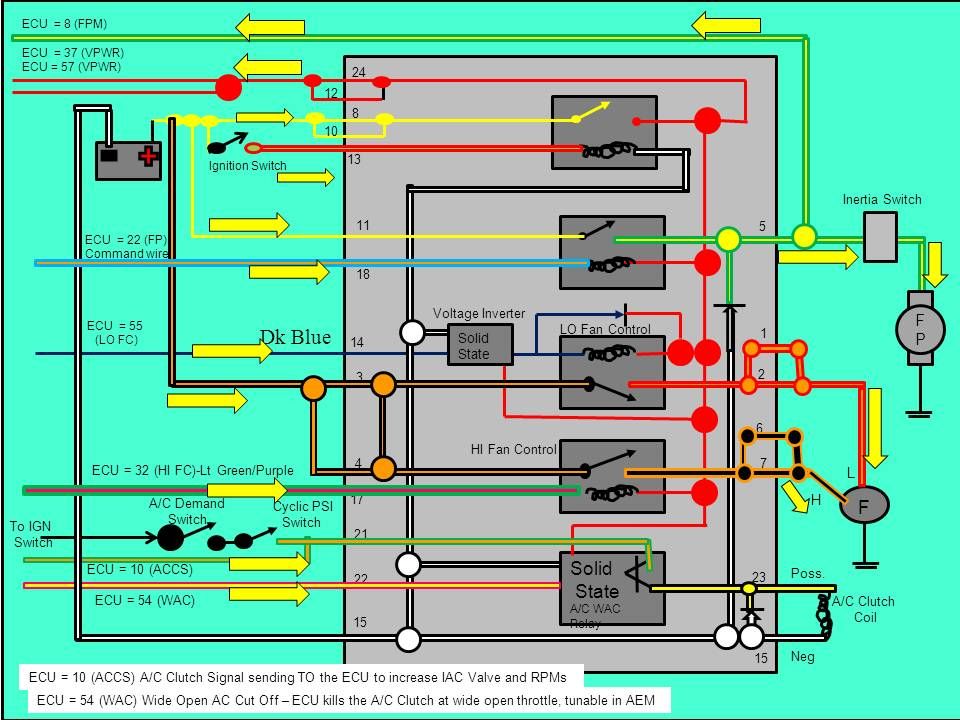
            Thanks for the responses guys. While I have the dash our I am thinking of ditching the Constant Control Relay Module and go to individaul relays instead. The CCRM manages the ECU power, Fan high and low sides, A/C compressor and fuel pump.

            I want to set up on individual relays.
            Fuel pump - I have the Racetronix direct power relay harness
            Electric Vacuum pump - I have the Racetronix direct power relay harness also. It uses a Hobbs switch so it is a completed ground to power the relay to power pump.
            ECU - should be a pretty simple, key on 12v to trigger.


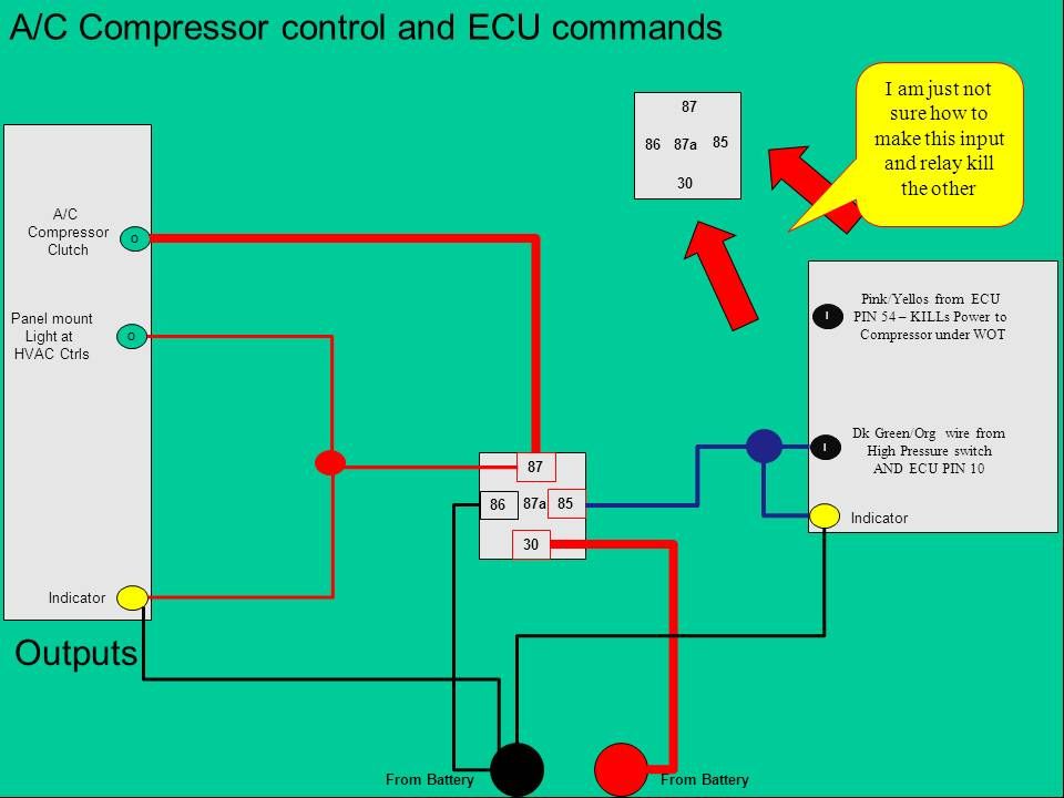
            A/C - power to clutch and integrate a A/C high pressure cutout fan switch/

            The internal to the CCRM uses a Solid State Relay - who can teach me the difference in a solid state and a regular Bosch relay?

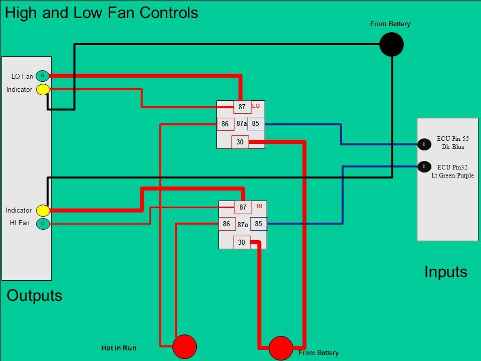
            2 speed Fan - I can control both sides of the fan with the AEM ECU but power needs to be a huge 8ga or 10ga wire and draws a fuck ton of amps from what I hear. Again the CCRM uses a relay for high and low side inside along with a solid state too.

            In my searches on line I have ran across these guys also www.leashelectronics.com
            Fuck you. We're going to Costco.

            Comment


            • #7
              That is exactly what I did with our car. The CCRM had the cooling fan, A/C, ECU, and fuel pump relay all in one box and they fail all the time. I ditched the box and put everything on individual 40amp relays (70amp for the cooling fan). I do it just like Brooks for exactly the same reason. The coil/switch power is derived from the same place or fuse as the main power for each relay. That way if there is a fault it not only clears a fuse it also turns off the relay.

              A solid state relay has no moving parts and uses a semi-conductor device (SCR usually) that is either on/conductor or off/non-conductive for a specific operating voltage. They can last longer and are much faster, but they are more $$$. Mechanical relays are cheap and work just fine for automotive use.

              Comment


              • #8
                Originally posted by jw33 View Post
                That is exactly what I did with our car. The CCRM had the cooling fan, A/C, ECU, and fuel pump relay all in one box and they fail all the time. I ditched the box and put everything on individual 40amp relays (70amp for the cooling fan). I do it just like Brooks for exactly the same reason. The coil/switch power is derived from the same place or fuse as the main power for each relay. That way if there is a fault it not only clears a fuse it also turns off the relay.

                A solid state relay has no moving parts and uses a semi-conductor device (SCR usually) that is either on/conductor or off/non-conductive for a specific operating voltage. They can last longer and are much faster, but they are more $$$. Mechanical relays are cheap and work just fine for automotive use.

                http://www.ssousa.com/appnote040.asp
                What kind of beer do i need to put in my fridge to get you to come over in April? lol

                I have already gone through the ECU harness once and pulled everything that was not tied to running the injectors, coils (LSx COP), ECT, IAT, TPS, MAP, crank/cam sensor, IAC, VSS, fuel pump, fan and A/C. The only thing going through the firewall grommet for the ECU harness is the CCRM and the ECU power wires. I would love to ditch it all.

                what do you think about this package


                Did you guys use the factory fan? I hear it can be upgraded to 5,000cfm but can not find the instructions. Something about they use a different motor on the same fan housing and blades.
                Fuck you. We're going to Costco.

                Comment


                • #9
                  Originally posted by jw33 View Post
                  That is exactly what I did with our car. The CCRM had the cooling fan, A/C, ECU, and fuel pump relay all in one box and they fail all the time. I ditched the box and put everything on individual 40amp relays (70amp for the cooling fan). I do it just like Brooks for exactly the same reason. The coil/switch power is derived from the same place or fuse as the main power for each relay. That way if there is a fault it not only clears a fuse it also turns off the relay.

                  A solid state relay has no moving parts and uses a semi-conductor device (SCR usually) that is either on/conductor or off/non-conductive for a specific operating voltage. They can last longer and are much faster, but they are more $$$. Mechanical relays are cheap and work just fine for automotive use.

                  http://www.ssousa.com/appnote040.asp
                  From what I can find people were still blowing 70amp relays with these fans. Would this be overkill for that circuit and I imagine I would have to have two of them, one for each speed.
                  Shop for Relays & Kits - Automotive from top manufacturers like from a trusted source.
                  Fuck you. We're going to Costco.

                  Comment


                  • #10
                    How many items would you run through a single SPDT Bosch 40amp relay?

                    LSx coils (through a tach adapter), ECU, Dash Gauges on one?
                    Fuck you. We're going to Costco.

                    Comment


                    • #11
                      That fuse box looks really nice and I like the idea of a big 100 amp relay for the cooling fan. I'm not exactly sure what the fan(s) pull current wise. I'm going to put a meter on ours and find out for sure. I'd be real surprised if it was greater than 40-50 amps except maybe for a brief moment on start-up. FWIW our car is a '91 2.3 car and I don't know what fan is on it, but it is a pretty big OEM fan from something ford. A single 40-amp relay should be enough to run those three things through.

                      Also on our car the ECU controls the fuel pump relay by sending a ground to the fuel pump relay coil. I thought your car was running some kind of stand alone aftermarket EFI? If so shouldn't that ECU be controlling the fuel pump already?

                      Comment


                      • #12
                        Originally posted by jw33 View Post
                        That fuse box looks really nice and I like the idea of a big 100 amp relay for the cooling fan. I'm not exactly sure what the fan(s) pull current wise. I'm going to put a meter on ours and find out for sure. I'd be real surprised if it was greater than 40-50 amps except maybe for a brief moment on start-up. FWIW our car is a '91 2.3 car and I don't know what fan is on it, but it is a pretty big OEM fan from something ford. A single 40-amp relay should be enough to run those three things through.

                        Also on our car the ECU controls the fuel pump relay by sending a ground to the fuel pump relay coil. I thought your car was running some kind of stand alone aftermarket EFI? If so shouldn't that ECU be controlling the fuel pump already?
                        I am running the AEM direct plug-n-play ECU. It controls everything as if you pull a factory ECU and drop it in, load file and fire it up.

                        From what I have found, the factory 94/95 Mustang fan pulls 18amperes and 36amperes. I am contemplating buying a Mark VIII fan which pulls 4,500-5,000cfm, building my own shroud and grafting the fan into it using as little of the factory housing if any at all. Off tangent, then also box in my radiator/intercooler opening.

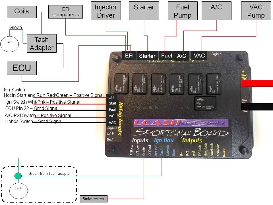
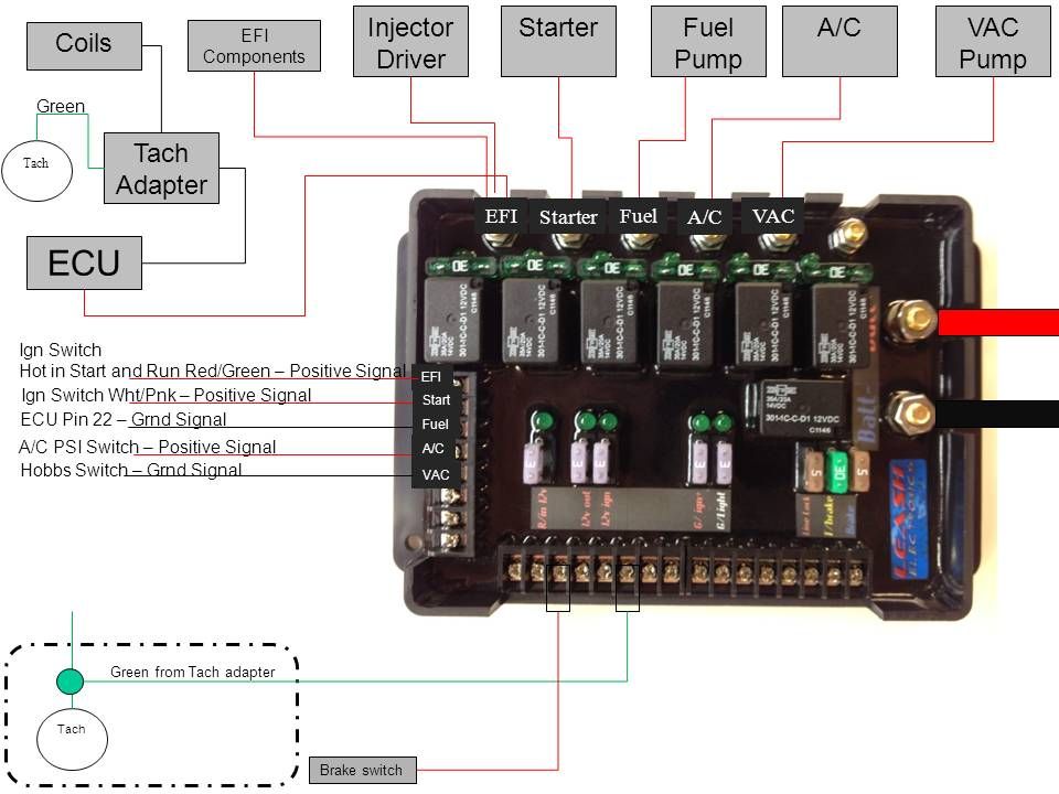
                        Here is the factory CCRM for a 94/95 Mustang. They are prone to failure and they stretch my ECU harness and body harness all over the damn front end. I want to fix that and organize and graft all my other relays into one consolidated area.


                        Hi and Lo fan controls solution


                        A/C solution so far. Just can not figure out the WAC circuit to kill the main relay.


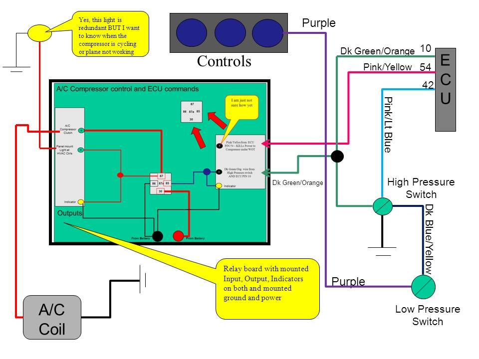
                        My first draft before I ran across the Leash stuff.


                        I have been playing, a little too much actually, but I have built a board off their site, just need to see if he can make it happen and help me figure out the A/C relay situation.


                        Last edited by KBScobravert; 02-27-2013, 07:52 AM.
                        Fuck you. We're going to Costco.

                        Comment


                        • #13
                          the leash electronic stuff is nice
                          903-870-8109

                          Thank you:
                          2JM Diesel & Fabrication - for the chassis and tuning
                          Freak Show Performance - for the great transmission
                          Jimmy Patton for the pit help
                          Chris Fowler for the motor work
                          TRZ Motorsports - thanks Mike
                          NRC Motorsports - thanks Bob
                          Team Z Motorsports - thanks Dave
                          Forced Inductions - thanks Jose
                          Work Turbochargers - thanks Reed

                          Comment


                          • #14
                            All that wiring makes my head hurt, How you guys do that is beyond me. Props to you for figuring all that out
                            GOD BLESS TEXAS
                            August Landscaping
                            214-779-7278
                            Seb's high class.
                            He'll mow your grass.
                            He'll kick your ass.
                            And while his kidney stones pass,
                            He'll piss in a glass!

                            Comment


                            • #15
                              Single Pole Double Throw (SPDT), Single Pole Single Throw (SPST) Automotive Relays

                              I have SPDT relays and plugs; several of them in kit form to build out how I want.

                              (Single Pole Double Throw Relay) an electromagnetic switch, consist of a coil (terminals 85 & 86), 1 common terminal (30), 1 normally closed terminal (87a), and one normally open terminal (87) wouldnt it being commonly closed power my compressor? (30 getting voltage from the pressure switch being sent straight to 87a and then to compressor?(Figure 1).

                              When the coil of an SPDT relay (Figure 1) is at rest (COIL not energized), the common terminal (30) and the normally closed terminal (87a) have continuity to send power to my compressor. When the coil is energized, the common terminal (30) and the normally open terminal (87) have continuity Removing power to my compressor.

                              The diagram below center (Figure 2) shows an SPDT relay at rest, with the coil not energized. The diagram below right (Figure 3) shows the relay with the coil energized. As you can see, the coil is an electromagnet that causes the arm that is always connected to the common (30) to pivot when energized whereby contact is broken from the normally closed terminal (87a) and made with the normally open terminal (87).

                              When energizing the coil of a relay, polarity of the coil does not matter unless there is a diode across the coil. If a diode is not present, you may attach positive voltage to either terminal of the coil and negative voltage to the other, otherwise you must connect positive to the side of the coil that the cathode side (side with stripe) of the diode is connected and negative to side of the coil that the anode side of the diode is connected.
                              Last edited by KBScobravert; 02-28-2013, 01:25 AM.
                              Fuck you. We're going to Costco.

                              Comment

                              Working...
                              X